Yagi Build
03/03/15 13:26 Filed in: Antennae
To get ready for the 2M competitions I got together with Martin to make up a couple of 9 element Yagi's to Justin, GØKSC's plans.
You will find details on his website
We also sells ready built antennas for those not wanting to make them up. Innovantennas
So how did we go about it:
First off you have to decide what you are going to build. We went for a loop fed yagi with a nice 14dBi gain and a 4.5m boom. All the dimensions are on the website as are the suggested tube dimensions. You need to decide on what boom you are going to use and go and order the aluminium.
We went to Aluminium Warehouse via the internet. There is a carriage charge so if you are going to make a few aerials then it pays to buy all you need in one go. You also need to order the insulators from Justin to match the tube size that you have ordered.
When it comes you will need some tools. All pretty basic, saw, rule and the usual soldering stuff we all have. It pays to have a couple of more specialist tools such as a rivnut (or captive nut) installation tool a, pipe cutter and a tube bender. You can get away without these by buying the loop ends from Justin and fixing the insulators with self tappers.
All set? Then off we go.
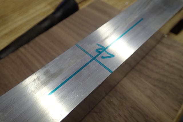
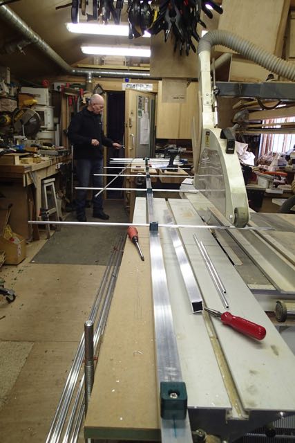
1 Setting Out
All projects start with reading and understanding the plans and measuring everything out twice before committing to drilling holes.
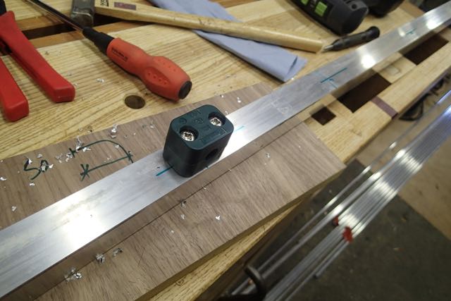
Mark the actual positions of the elements down the boom and mark the centre lines for the fixings. This one is marked L2 or the 2nd loop element.
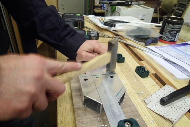
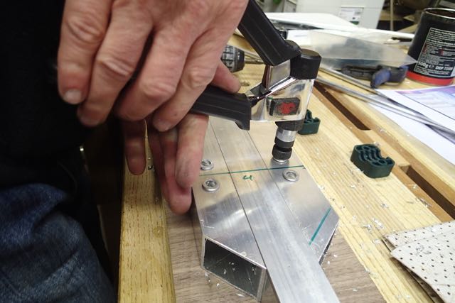
2 Riv nut fixing
I like the idea of riv nuts as you can take the elements off for transport and still have a secure fixing. Yes....we are using these for portable operation.
So look at the insulator and line up the bit where the element goes with the line you have marked. The line is NOT where the hole goes. It is where the element goes.
Some insulators have two holes and some one. Make sure you have the right ones. On ours the doubles were for the fed loop and singles for the elements.
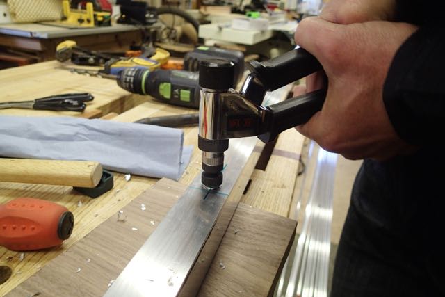
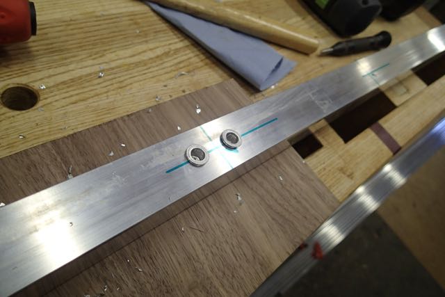
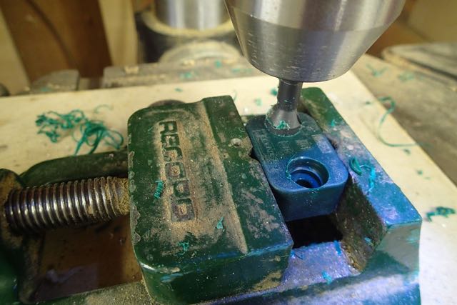
You will need to open up the bottom hole in the insulator so it sits flush on the boom over the riv nut
This is what we are aiming for and below is how we get there in more detail.
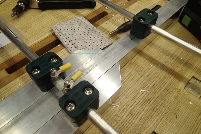
3 Driven Element Fixing
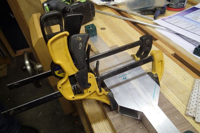
The driven element is like a dipole and has an insulator between a split tube. The supports will be off each side of the boom so we need to widen it at the driven element.
You will have some of the boom left over which you can chop into two bits and then angle the ends at 45 degrees.
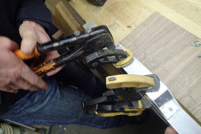
Then pop rivet these on where the 45 degree bit is cut
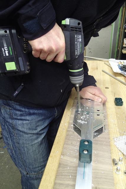
Then set out the insulators again and drill holes for them
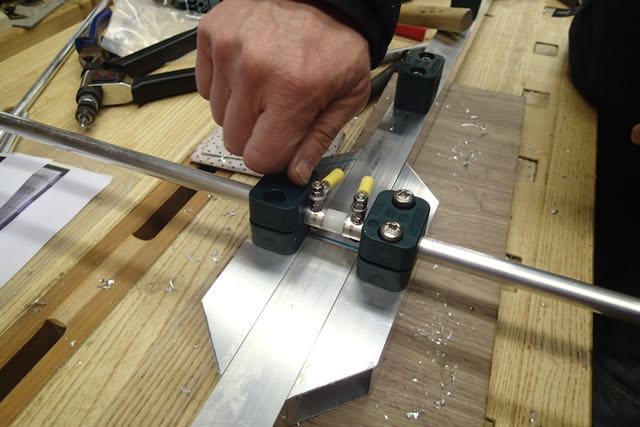
4 Driven Element
You should have also brought Justin's insulator for the driven element to make life easy. Fit it into the two lengths of tube you have cut and drill through for the connecting bolts.
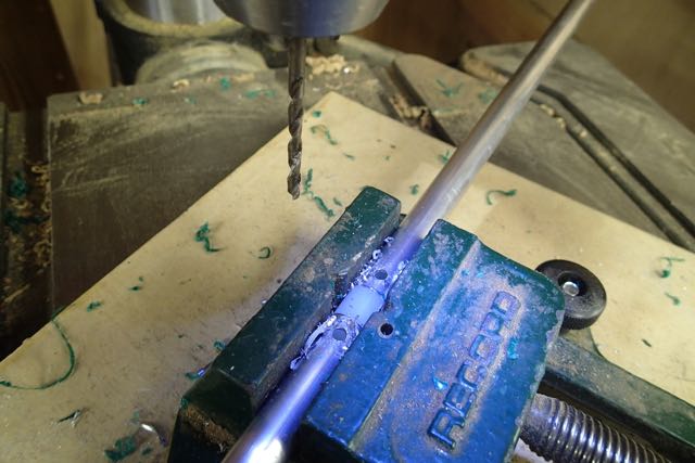
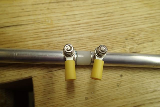
You can then fix that into the insulators. It should look something like this
5 Loop Ends
You might have brought these from Justin. I did with my first beam. Or you have bent them using a tube bender (mine is a brake pipe bender) to EXACTLY the right dimensions
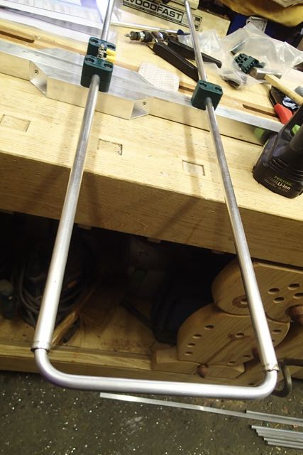
These are the bits you need to adjust at the end to tune the antenna, so make sure they slide in and out. Once you have tuned them you can pop rivet or self tap in place.
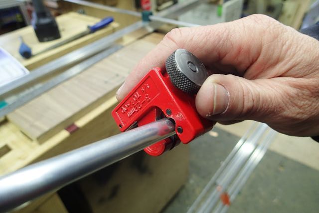
6 Elements
Next bit is easy. Cut the elements to the right lengths and fit them into the insulators. Using a small tube cutter makes a neat job of it.
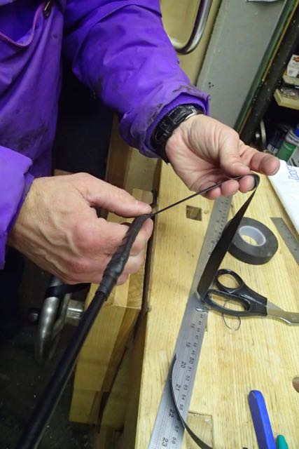
7 Balun
I should have taken more pictures of this but we were getting excited about testing!
Justin has details of something called Pawsey Stub. Don't ask me how it works - i'm only an intermediate!!. We just followed the instructions and bingo it works.
More radio magic.
The idea is that you connect the centre coax feed point onto the loop back to the braid of the coax by 1/4 wave. That needs to be exact and, here you are going to be really impressed, because you need to take into account the velocity factor. Of course. You find that in the data from whoever makes your coax. It is the amount that the coax slows down the speed of the wave - so if you have more than 1 it is not the right figure.
A quick calculation
speed of light/frequency x velocity factor x quarter (WAVE)
or in our case
300/144.3 x .83 x .25 = 43.1cm
Cut a lengthy of wire to that length and join the core at the feed point back to the shield. I stripped off a small bit of the covering and soldered it on and then wrapped the lot in self amalgamating tape.
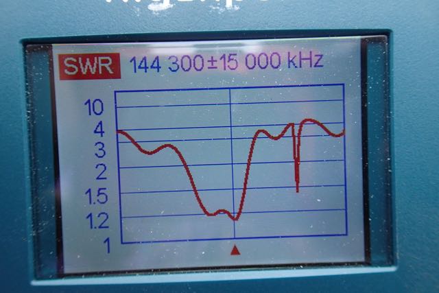
8 Testing Testing......
As yet I haven't got a mast to put it on so we did a quick test in the rain on a 10' pole.
You need to adjust the loops that you bent to give the right SWR and we ended up taking 10mm off ours as we made them oversize to start with. It's easier to cut off than to stick back on!
Heres what we got.
And here it is.
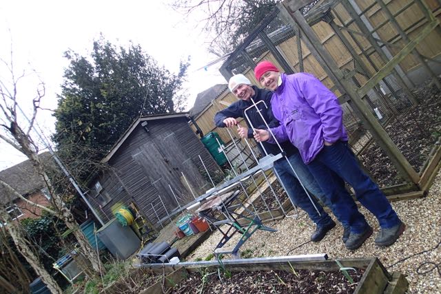
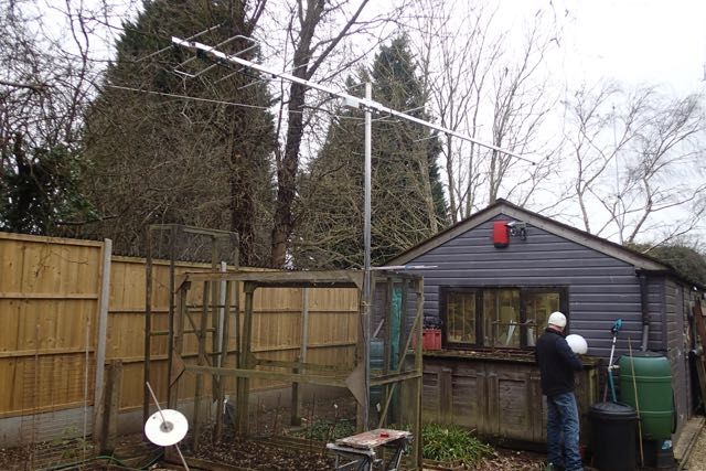
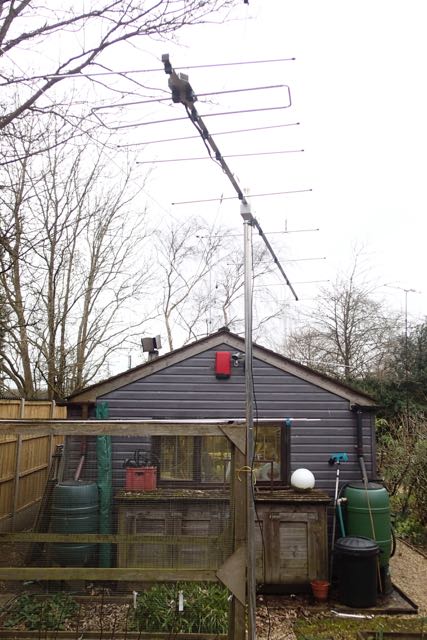
We will update the blog when it has been tested properly. But we are excited that they are going to be so good!
You will find details on his website
We also sells ready built antennas for those not wanting to make them up. Innovantennas
So how did we go about it:
First off you have to decide what you are going to build. We went for a loop fed yagi with a nice 14dBi gain and a 4.5m boom. All the dimensions are on the website as are the suggested tube dimensions. You need to decide on what boom you are going to use and go and order the aluminium.
We went to Aluminium Warehouse via the internet. There is a carriage charge so if you are going to make a few aerials then it pays to buy all you need in one go. You also need to order the insulators from Justin to match the tube size that you have ordered.
When it comes you will need some tools. All pretty basic, saw, rule and the usual soldering stuff we all have. It pays to have a couple of more specialist tools such as a rivnut (or captive nut) installation tool a, pipe cutter and a tube bender. You can get away without these by buying the loop ends from Justin and fixing the insulators with self tappers.
All set? Then off we go.
1 Setting Out
All projects start with reading and understanding the plans and measuring everything out twice before committing to drilling holes.
Mark the actual positions of the elements down the boom and mark the centre lines for the fixings. This one is marked L2 or the 2nd loop element.
2 Riv nut fixing
I like the idea of riv nuts as you can take the elements off for transport and still have a secure fixing. Yes....we are using these for portable operation.
So look at the insulator and line up the bit where the element goes with the line you have marked. The line is NOT where the hole goes. It is where the element goes.
Some insulators have two holes and some one. Make sure you have the right ones. On ours the doubles were for the fed loop and singles for the elements.
You will need to open up the bottom hole in the insulator so it sits flush on the boom over the riv nut
This is what we are aiming for and below is how we get there in more detail.
3 Driven Element Fixing
The driven element is like a dipole and has an insulator between a split tube. The supports will be off each side of the boom so we need to widen it at the driven element.
You will have some of the boom left over which you can chop into two bits and then angle the ends at 45 degrees.
Then pop rivet these on where the 45 degree bit is cut
Then set out the insulators again and drill holes for them
4 Driven Element
You should have also brought Justin's insulator for the driven element to make life easy. Fit it into the two lengths of tube you have cut and drill through for the connecting bolts.
You can then fix that into the insulators. It should look something like this
5 Loop Ends
You might have brought these from Justin. I did with my first beam. Or you have bent them using a tube bender (mine is a brake pipe bender) to EXACTLY the right dimensions
These are the bits you need to adjust at the end to tune the antenna, so make sure they slide in and out. Once you have tuned them you can pop rivet or self tap in place.
6 Elements
Next bit is easy. Cut the elements to the right lengths and fit them into the insulators. Using a small tube cutter makes a neat job of it.
7 Balun
I should have taken more pictures of this but we were getting excited about testing!
Justin has details of something called Pawsey Stub. Don't ask me how it works - i'm only an intermediate!!. We just followed the instructions and bingo it works.
More radio magic.
The idea is that you connect the centre coax feed point onto the loop back to the braid of the coax by 1/4 wave. That needs to be exact and, here you are going to be really impressed, because you need to take into account the velocity factor. Of course. You find that in the data from whoever makes your coax. It is the amount that the coax slows down the speed of the wave - so if you have more than 1 it is not the right figure.
A quick calculation
speed of light/frequency x velocity factor x quarter (WAVE)
or in our case
300/144.3 x .83 x .25 = 43.1cm
Cut a lengthy of wire to that length and join the core at the feed point back to the shield. I stripped off a small bit of the covering and soldered it on and then wrapped the lot in self amalgamating tape.
8 Testing Testing......
As yet I haven't got a mast to put it on so we did a quick test in the rain on a 10' pole.
You need to adjust the loops that you bent to give the right SWR and we ended up taking 10mm off ours as we made them oversize to start with. It's easier to cut off than to stick back on!
Heres what we got.
And here it is.
We will update the blog when it has been tested properly. But we are excited that they are going to be so good!
blog comments powered by Disqus